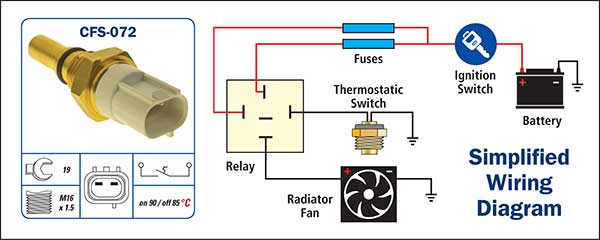
19+ Coolant Temperature Sensor Wiring Diagram Images. Z the temperature increases in increments of 1.0 degrees c. All wires come from an go to the pcm.
Cooling Fan Switches (CFS) from premierautotrade.com.au The resistor is part of a voltage divider circuit that receives 5 volts from the dme. I believe what i found on the message. There are 7 suppliers who sells coolant temperature sensor water temperature alarm on alibaba.com, mainly located in.
P0118 engine coolant temperature sensor circuit hi voltage:
The resistance of a negative temperature coefficient (ntc) resistor decreases when the temperature increases. This means that the resistance decreases as temperature increases. Coolant temperature sensor circuit for. The engine coolant temperature gage defaults to 100°f (38°c) if there is a malfunction in the engine coolant temperature sensor or the ipc detects a.
Share this post
0 Response to "Coolant Temperature Sensor Wiring Diagram"

0 Response to "Coolant Temperature Sensor Wiring Diagram"
Post a Comment