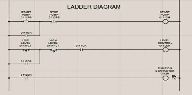
Control Relay Circuit Diagram
50+ Control Relay Circuit Diagram Pictures. Since relays are switches, the terminology applied to switches is also step 3: Electromechanical relays may be connected together to perform logic and control functions, acting as logic elements much like digital gates (and, or, etc.).

Parts list for the proposed solid state relay circuit.
In this phase controller internally install a relay and circuit which measure the phases and switch off the relay when one phase is missing to the phase failure circuit. A relay is actually a switch which is electrically operated by an electromagnet. A relay is an electromagnetic switch that is used to turn on and turn off a circuit by a low power signal, or where several circuits must be controlled by one the diagram shows an inner section diagram of a relay. Savesave schematic diagram of the circuit relay control for later.
0 Response to "Control Relay Circuit Diagram"
Post a Comment