38+ Complex Motor Control Wiring Diagrams Pics. Schematic diagrams show how a circuit works electrically while a wiring diagram shows how a circuit is physically wired. In line with the green revolution, electric motor control is moving very quickly in the direction of higher efficiency for motors and drives.
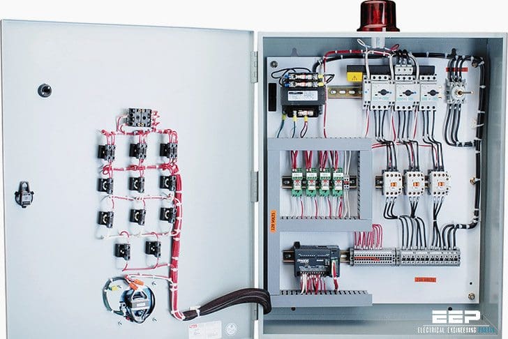
Basic wiring for motor control - Technical data guide | EEP from electrical-engineering-portal.com Syed the link to download the vi (wiring diagram) is not working. When you select to use step/dir motor like this above, the spindle speed control by step. The card supplied by usb, has installed a power module, the maximum output 5.nmotion cnc controller support step/dir motor as spindle.
The card supplied by usb, has installed a power module, the maximum output 5.nmotion cnc controller support step/dir motor as spindle.
Note that all grounded terminals are connected together. Such a company started production in 1987. While the internal details of a vfd are quite complex, the basic operating principle (and rationale) is not. However, the commutator has brushes that wear, so they are much less often used for.
Share this post
0 Response to "Complex Motor Control Wiring Diagrams"

0 Response to "Complex Motor Control Wiring Diagrams"
Post a Comment